Are you Searching for one of these ? click the link below and call this number +91 8128381431 for #PET #recycling, PU/TPU extrusion, WPC extrusion, Nylon extrusion and many more things like new product development from PET/Polyester recycling.
Polystyrene (PS) is a thermoplastic designed for applications requiring excellent electrical and mechanical properties together with good process ability. Polystyrenes have well-balanced physical properties and are generally transparent, but available in various colors.
JEWEL PACKAGING USING GPPS CASE
Unfilled polystyrene has a sparkle appearance and is often referred to as crystal PS or general purpose polystyrene (GPPS). Because of the brittleness of crystal polystyrene, styrene is frequently polymerized in the presence of dissolved polybutadiene rubber to improve the strength of the polymer.
GPPS made CD cover
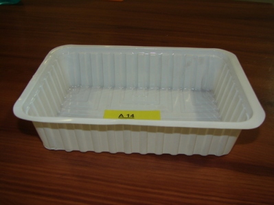
HIPS is often specified for low strength structural applications when impact resistance, machinability, and low cost are required. It is frequently used machining pre-production prototypes since it has excellent dimensional stability and is easy to fabricate, paint and glue. Natural (translucent white) HIPS is FDA compliant for use in food processing applications.
made of HIPS
Packaging is one of the primary uses of polystyrene, but there are different types of packaging as well. It is important to know the difference between some of these polystyrenes, namely General Purpose Polystyrene (GPPS) and High Impact Polystyrene (HIPS).
General Purpose Polystyrene, also known as crystal-clear polystyrene, is fully transparent and rigid, and is widely used in food packaging applications or jewel cases. Back in the day, the most common application of GPPS was seen in the cases that enclosed CDs. Apart from being FDA compliant, it is also low-cost, X-ray resistant, free from odor and taste, and easy to process.
High Impact Polystyrene, on the other hand, is impact resistant at the cost of not being naturally clear or transparent. It can be easily painted on and glued. It has economical and easy manufacturability but is generally more expensive than GPPS. HIPS has a matte finish and is a preferred material for thermoforming. A common application of HIPS is yogurt cups.
While HIPS has higher impact strength, GPPS is better suited for storage and packaging purposes because of its transparency. GPPS can be molded into exciting shapes, such as that of a treasure chest or a heart to serve as candy boxes for gifting.
Here are some other properties that highlight the advantageousness of GPPS:
FDA compliant—non-toxic
Good dimensional stability
Low cost compared to other materials
Easy to paint, glue, and print on
Excellent aesthetic qualities
PS – Polystyrene (HIPS, GPPS)
Polystyreneis one of the oldest thermoplastic polymers dating back to the 1930. After some mergers and takeovers, the most important polystyrene producers are Trinseo, Styrolution and Total.
HIPS, high impact polystyrene, is polystyrene which has butadiene rubber as impact modifier, giving the material good impact performance, but losing the transparency.
Polystyrene is easy to process, has a nice gloss and it is still the most preferred material for thermoforming. The most well known polystyrene application is yoghurt cups.
Another big thermoforming application of polystyrene is the inner liners of refrigerators and freezers, for which special high ESCR (environmental stress crack resistance) grades have been designed.
Polystyrene (PS) is made by polymerizing styrene monomer, polymerization by a variety of synthetic methods. PS is a non-crystalline thermoplastic resin, can be divided into general purpose polystyrene (GPPS), high impact polystyrene (HIPS) and expanded polystyrene (EPS). Difference of GPPS, HIPS and EPS is: GPPS has high transparency, good gloss, HIPS has general brightness, toughness is little less than ABS, surface is bright after the fire, has styrene taste. HIPS truncated face pale, but GPPS is not, and EPS is mainly used for foam.
GPPS is a general purpose polystyrene, density of GPPS is 1.04 to 1.09, the transparency is up to 88% -92%, refractive index is 1.59 to 1.60, and such a high refractive index made it has a good gloss, and a decorative effect. Good dimensional stability. Common Range: Commodity: cups, all kinds of boxes, toothbrushes, combs, food containers, pens.
HIPS is high impact polystyrene, polystyrene impact polystyrene products can be produced by adding the polybutyl rubber particles approach.
HIPS is a modified material of PS, divided rubber composition containing 5-15%, the toughness of PS increased about four times the impact strength is greatly increased. PS molding and coloring are strong. HIPS water absorption is low; processing may not need to pre-dry.
HIPS is opaque milky white beads or particles which can be any color, rigid, easy processing, high strength. The impact strength of different, rubber content is different. HIPS can be divided into general and ultra-high impact impact several levels. With the decreased improvement of impact strength and tensile strength transparency. HIPS is mainly used for packaging materials, such as food, cosmetics, daily necessities, machinery and instruments and stationery packaging; can be molded using a variety of processing methods.
Expanded Polystyrene (EPS) is a lightweight polymer. It is the use of a polystyrene resin, a foaming agent was added, while heating to soften, to produce gas and form a rigid closed cell foam structure. This uniform closed cavity structure made EPS has a low water absorption, good insulation, light weight and high mechanical strength and other characteristics.
EPS is determined by the density of the expanded polystyrene particles of multiple forming stages, generally between 10 to 45 kg / m3, EPS apparent density is generally used as a project which is in 15 to 30 kg / m3. Currently density of EPS used as a light filling in road works is 20kg / m3, as an ordinary road filler 1% to 2%. Density is an important indicator of EPS; its mechanical properties are related to its almost proportional to the density.
Thermoforming is a manufacturing process where a plastic sheet is heated to a pliable forming temperature, formed to a specific shape in a mold, and trimmed to create a usable product. The sheet, or “film” when referring to thinner gauges and certain material types, is heated in an oven to a high-enough temperature that permits it to be stretched into or onto a mold and cooled to a finished shape. Its simplified version is vacuum forming.
In its simplest form, a small tabletop or lab size machine can be used to heat small cut sections of plastic sheet and stretch it over a mold using vacuum. This method is often used for sample and prototype parts. In complex and high-volume applications, very large production machines are utilized to heat and form the plastic sheet and trim the formed parts from the sheet in a continuous high-speed process, and can produce many thousands of finished parts per hour depending on the machine and mold size and the size of the parts being formed.
Thermoforming differs from injection molding, blow molding, rotational molding and other forms of processing plastics. Thin-gauge thermoforming is primarily the manufacture of disposable cups, containers, lids, trays, blisters, clamshells, and other products for the food, medical, and general retail industries. Thick-gauge thermoforming includes parts as diverse as vehicle door and dash panels, refrigerator liners, utility vehicle beds, and plastic pallets.
In the most common method of high-volume, continuous thermoforming of thin-gauge products, plastic sheet is fed from a roll or from an extruder into a set of indexing chains that incorporate pins, or spikes, that pierce the sheet and transport it through an oven for heating to forming temperature.
The heated sheet then indexes into a form station where a mating mold and pressure-box close on the sheet, with vacuum then applied to remove trapped air and to pull the material into or onto the mold along with pressurized air to form the plastic to the detailed shape of the mold. (Plug-assists are typically used in addition to vacuum in the case of taller, deeper-draw formed parts in order to provide the needed material distribution and thicknesses in the finished parts.)
After a short form cycle, a burst of reverse air pressure is actuated from the vacuum side of the mold as the form tooling opens, commonly referred to as air-eject, to break the vacuum and assist the formed parts off of, or out of, the mold. A stripper plate may also be utilized on the mold as it opens for ejection of more detailed parts or those with negative-draft, undercut areas.
The sheet containing the formed parts then indexes into a trim station on the same machine, where a die cuts the parts from the remaining sheet web, or indexes into a separate trim press where the formed parts are trimmed. The sheet web remaining after the formed parts are trimmed is typically wound onto a take-up reel or fed into an inline granulator for recycling.
Most thermoforming companies recycle their scrap and waste plastic, either by compressing in a baling machine or by feeding into a granulator (grinder) and producing ground flake, for sale to reprocessing companies or re-use in their own facility. Frequently, scrap and waste plastic from the thermoforming process is converted back into extruded sheet for forming again.
In specific circumstances, Grooved Feed can increase output and reduce melt temperature. But these throats are not for every application.
There are basically two types of single-screw extruders, distinguishable primarily by their feed-throat design.
Most single-screw extruders have smooth-bore feed throats—basically a smooth pipe surrounding the rotating screw.
Extruders with smooth-bore feed throats are affected a number of ways by the resistance or “head” pressure against which the screw is rotating. As the head pressure increases, a reverse flow (or pressure flow) develops in the screw channels that subtracts from the output (or drag flow) while increasing the melt temperature (because the material is essentially being re-circulated back into the screw).
This can cause significant problems in extrusion processes that have inherently high head-pressure characteristics resulting from a narrow die gap, such as in blown film, extrusion coating, and thin-wall tubing.
With a smooth-bore feed throat, solids transport of material with the rotating screw is highly dependent on the friction of the polymer particles against the barrel wall.
Depending on the polymer and the temperatures, the feed efficiency is typically 15% to 30% based on the channel volume because of “slip” of the polymer particles on the feed-throat wall.
The second type of feed throat has grooves or interruptions machined into the feed-throat wall.
Extruders with grooved feed throats resist rotation of the solid polymer particles against the feed-throat wall.
This can increase conveying efficiency multiple times. Additionally, because the polymer is much more rapidly compacted into a solid and cannot slip on the feed-throat wall, the screw flights act as a spiral wedge multiplying the pressure development.
As this spiral block of polymer moves down the feed throat, it becomes highly pressurized compared with what occurs in a smooth-bore extruder.
In the absence of any melting, which reduces the pressure development, the pressure tends to rise exponentially with groove length. Groove lengths are usually 4D or less because of the exponential rise in pressure and the difficulty in preventing melting from occurring over longer lengths.
Pressures exceeding 12,000 psi have been achieved at the end of the grooved section, so care must be exercised in design to prevent over-pressurization of the barrel. That can be done modifying the design of the grooves themselves, or by designing a decompression section in the screw.
This pressure offsets, and in many cases can exceed, the pressure at the discharge. The grooved feed throat is intensively cooled so the material won’t prematurely melt and hinder pressure development.
Since the barrel is essentially a pipe, the pressure from the grooved feed throat transfers through the barrel, counteracting the discharge-pressure resistance. If the feed-throat pressure development exceeds the discharge pressure, the output will exceed the drag flow, resulting in further throughput gains.
Before deciding to move to a grooved feed throat, weigh the advantages against the disadvantages for your process.
The advantages of grooved feed throats:
Reduction or elimination of the effect of high head pressure, resulting in higher output.
• Reduction in melt temperature at same output.
• Stabilized output.
• Not very sensitive to barrel temperatures.
The disadvantages of grooved-feed throats:
• Proportionally more drive power required.
• Performance very sensitive to particle characteristics.
• Generally not suitable for most regrind due to plugging of the grooves.
• Does not work on “soft” polymers like many TPEs due to plugging of the grooves.
• Not as good for compounding additives without extensive mixing sections due to higher specific output.
• Not generally suitable for powdered polymers or additives.
• Can have accelerated screw/barrel wear without accurate balanced design due to higher pressures in feed section.
• Can be unstable with “hard” polymers such as polycarbonate.
• Requires higher volume of cold water for cooling.
• Requires a special screw design, unlike those used for smooth bore extruders.
Grooved-feed technology was developed in Germany in the early 1960s and has been more widely used in Europe than in other parts of the world. However, this design is the standard everywhere for much of HDPE pipe and HMW-HDPE blown film production.
Now, grooved-feed designs are more commonplace. Many barrier blown film lines, for example, are equipped entirely with grooved-feed extruders.
Meantime, there also have been many developments in feed-throat “surface improvements.” Though not to be confused with traditional grooved feed throats, these surfaces aim to improve friction at the feed-throat wall by using shallow grooves of various designs. They’ve been shown to significantly improve output with polymers having low feed efficiency, and are effective when processing regrind and fillers. However, where screw design is concerned, they follow the principles of smooth-bore feed throats.
Grooved feed throats have their pros and cons. As a processor, weigh the promise of improved output and lower melt temperature against the disadvantages. Consider them only for situations where they are beneficial overall to the process. Don’t think of them as general-purpose extruders.
Understanding groove feed
With many polymers, grooved-feed extruders produce 20-40% higher output per rpm than the same diameter extruder with a smooth feed bore. A grooved feed section improves solids conveying and increases extruder pumping action, thereby raising output at a given extruder rpm, reducing energy put into the polymer, and lowering melt temperature.
Finding the right groove
The grooved feed section of a 90 mm extruder may have eight to 18 grooves evenly distributed around the feed bore.
In general, higher viscosity resins like HMW-HDPE or polypropylene benefit more from lots of grooves; lower viscosity resins use fewer grooves. Using too many grooves can feed resin to the mixing stage of an extruder too fast and cause melting inefficiencies and mixing problems.
Grooves are typically 0.15-0.3 in. wide and deepest toward the back of the feed area. Starting depth is 0.12-0.37 in. and tapers to zero in three or four diameters past the downstream end of the feed opening. Grooves run parallel to the screw axis.
Feed sections are designed with cooling jackets to provide intensive water flow around the feed opening and the extended grooved section. This prevents resins from melting in the grooves. Conversely, to reduce the feeding action of the grooves and slow the pumping of materials like nylon or polycarbonate, heat (93-148 C or higher) can be applied to the grooves. This starts the resin melting, and avoids a dangerous pressure buildup at the end of the grooves.
Another alternative is short grooves that extend only half a diameter into the barrel. For processes that run up to 50% regrind, short grooved-feed sections can improve feeding consistency. But short grooves won’t work on HMW-HDPE. And high regrind percentages of any low-bulk-density material (10 lb/cu ft or less) will also feed poorly unless the fluff is compacted before it is added.
Screw choices for grooves
Long grooves are always hardened either by nitriding or, for more abrasive resins, by coating them with tungsten carbide.
Shorter groove sections typically aren’t hardened. Screws are often hardened with the same substance as the grooves for compatibility and even wear.
It’s not common to change the grooved sleeve in order to process different resins. The sleeve is replaced only because of wear–i.e., every 5-10 years. Of course, the screw can be changed to handle different resins with the same grooved feed.
Choice of hardening material depends not only on the abrasiveness of the polymer but on the early screw depth. The original metering-screw designs of the 1960s and ’70s sometimes included one or more mixing sections and a uniform channel depth throughout the screw length. These designs saw the highest pressure build-up–and the greatest need for hardening–at the end of the grooves.
Later grooved-feed screw designs from the 1980s included melt-separating barrier sections with deeper screw channels at the end of the grooves to relieve pressure. These may not need tungsten carbide grooves for most polymers. However, those screws should have shallower flight channels than those used with smooth bores, or else output efficiency may drop to the point where the grooves no longer improve feeding.
Grooved-feed screws today are relatively shallow throughout the feed channels to provide more efficient feeding. On a 3.5-in. screw, channels with a grooved feed will usually be 0.25-0.4 in. deep, half the depth of channels with a smooth bore (0.6-0.7 in.). The shallower screw channels for grooved feed keep the resin solid-bed height short and maintain high forward force in the grooves. This also builds up enough pressure at the end of the grooves to achieve adequate compression in the channels entering the heated extruder barrel.
In the 1950s and ’60s, screw channels with grooved feeds were the same depth throughout the length of the screw, whereas screw channels with a smooth bore get shallower as the polymer moves toward the screw tip. Small screws (1.5 in. diam. and smaller), however, generally have the same shallow feed depth whether for grooved or smooth feed sections. Feed depth is as shallow as it is on European grooved-feed designs. This is why traditional smooth-feed screws on small extruders will respond to even short grooves better than larger extruders. Very small extruders (1 in. diam. and under) often require the help of grooves in solids conveying, since pellet size is large compared with screw flight depth.
Mechanical strength of the grooved-feed section must be high enough to handle high pressure on startup or with certain polymers. Pressures at the end of the grooved section can get as high as 15,000-20,000 psi. So equipment should be designed to take up to 30,000 psi, even though today’s groove and screw designs try to maintain feed pressures below 10,000 psi.
Pressure at the end of the grooved-feed section is often higher than at the die end, so screw performance is not sensitive to die pressure the way it is in smooth-bore extruders. Smooth-feed extruders operate against die pressures of 3000-4000 psi and must raise screw rpm to get the same output as they do at lower die pressure. The energy to pressurize the melt plus the energy from higher screw speeds on a smooth-feed extruder make operation difficult as melt temperature and pressure rise.
Grooved-feed extruders’ higher output per RPM requires a larger gear box than smooth-bore machines of similar diameter. It also takes more torque to start up or restart.
Right resins for grooves
Polyolefins are by far the most common polymers successfully processed with cooled grooved feeds. Since the 1980s, polymer developments have tended toward higher melt viscosities. Single-site catalysts make resins with higher molecular weights, improved properties, and much narrower molecular-weight distribution. But these polymers are more challenging to extrude. With many of these newer polymers, smooth-bore extruders struggle to maintain desired melt temperature as screw speed increases to raise output. So grooved feed is being looked at–and sometimes selected–to lower melt temperature.
Processors most likely to benefit from using grooves have dedicated operations using only one or two polyolefins at high output rates. Examples are lines running high-viscosity PE and PP for pipe, sheet, blown film, and blow molding. Materials with high melting points and higher crystallinity don’t work as well on grooved-feed extruders. Their compressibility and melting characteristics are different from polyolefins. To run them safely, feeding efficiency of the grooves must be reduced to protect the barrel and grooved section from pressure damage.
Smooth feed is generally better than grooved feed when you need to process a variety of polymers, use low-bulk-density regrind, and vary regrind particle size and/or percentage. Particle size of feed materials affects groove performance, so if no control is ensured over regrind percentages or particle size, a controlling weigh hopper or a melt pump is needed to ensure constant output. Smooth-feed extruders, with relatively deep feed channels, are less affected by regrind particle size and less susceptible to fluctuating regrind percentages. More disciplined operation is therefore required for a grooved-feed set-up.
Grooved-feed extruders perform best with precolored resin. Adding color masterbatch requires a higher level of mixing from the screw and higher melt temperatures, thus offsetting some of the benefits of grooved feed.
Smooth-feed extruders also do better with higher-melt-temperature polymers like nylon, PET, polycarbonate, and fluoropolymers. If these materials are to run on a grooved-feed machine, the grooves are typically heated. This reduces feeding efficiency because it allows some melting in the grooves. Also deeper screw feed channels can be used to reduce the tendency to overfeed the extruder.
Soft, gummy resins such as TP urethanes, other elastomers, and softer metallocene polymers also have difficulties in grooves if not cooled enough. Soft pellets can smear and fill the grooves, reducing forward force and/or causing gels in film.
Vented extrusion is also not a great choice for a grooved-feed extruder, since output is usually limited by the pumping capacity of the second stage. A very efficient first stage may produce enough output to flood vents or cause poor melting at vents. Melt at the vent must be complete enough to allow evacuation (usually under vacuum) of air, moisture, and resin volatiles.
To get high efficiency in extrusion there are lot of things we have to do.
When Quality people run line and manage operation they give high quality & stable process.
Successful extrusion is not about doing two or three things right—it’s about doing hundreds of things right.
Proper instrumentation is necessary to achieve efficiency in extrusion. In Extrusion the most critical process variables are
Melt pressure, Melt temperature, and Motor load.
These are very important symbol of the extrusion process. With these following more parameters above three must be continuously measured and monitored.
Barrel and die temperatures,
Screw speed,
Power consumption in each heating or cooling zone,
Ambient temperature,
Relative humidity,
Temperature of feedstock entering extruder,
Moisture level of feedstock entering extruder (if hygroscopic),
The feed-housing water flow rate plus inlet and outlet temperatures allow quantitative determination of the amount of cooling taking place. If the cooling channels in the feed housing build up with calcium deposits, heat transfer will gradually deteriorate, significantly affecting extruder performance. If the cooling rate of the feed housing is not measured, it is very difficult to relate deterioration in extruder performance to poor heat transfer in the feed housing.
GET DATA
Data acquisition (DA) capability is critical in developing a robust extrusion process, maintaining process consistency, optimizing the process, and troubleshooting efficiently. Fortunately, with today’s inexpensive computers and widely available DA software it is possible to install a highly capable DA system on existing extrusion lines. Unfortunately (and mystifyingly), relatively few processors take advantage of this capability.
Recently, I worked with a processor to install a PC-based DA system on a relatively old extrusion line. The cost of the DA system was less than $20,000. Within about three months the scrap rate on this line dropped from about 15% to 5%. As a result, the DA system paid for itself within a few months and now allows the processor to run at significantly reduced scrap rates all the time on every line.
The scrap rate was reduced because with the DA system the process could be optimized in a way that was not possible before. Also, problems that would lead to off-spec product could be identified immediately and corrected before off-spec product was actually produced. This is not rocket science! It is simply using tools that are readily available and using them efficiently. Old extrusion lines can often produce good products as long as they are well maintained and have good instrumentation and control with DA capability.
The consistency of the feed material and the flow of the feed material to the extruder are critical to achieving process stability. Variations in feed material (e.g., varying levels of regrind) invariably lead to variations in the extrusion process. Even seemingly minor issues like pellet size distribution can affect the process. Generally, a narrower pellet size distribution will enhance the stability of the extrusion process.
FEEDING OPTIONS
There are two basic feeding methods: flood feeding and starve feeding. In flood feeding the feed hopper is filled to a certain level, the material flows to the extruder in mass flow (most of the time), and the extruder takes in as much material as it can bite off. The screw channel tends to be filled completely almost right away .
Flood feeding fills the screw channels completely and takes advantage of the full length of the screw. It requires no extra feeding equipment, but offers reduced process control.
As a result, in flood feeding the effective length of the screw is more or less the same as the flight length of the screw.
In starve feeding the polymer is metered into the extruder by a feeding device.
2. Starve feeding requires a feeder but offers greater process control and tends to reduce melt temperatures.
There is no accumulation in the hopper; the material instead drops directly into the screw channel, and the screw channel is only partially full at the feed opening. As the material is conveyed forward the screw channel will become completely filled some distance downstream of the feed.
As a result, in starve feeding the effective length of the screw is less than the flighted length of the screw. An important advantage is that the effective screw length can be adjusted while the extruder is running. This allows broader process control than with flood feeding, where the effective length is not adjustable. Starve feeding is only beneficial if the extruder is long enough to achieve complete melting and effective mixing. Therefore, starve feeding generally will not give process improvements on short (25D long) extruders. Starve feeding requires a feeder, but it reduces motor load, melt temperature, and chances of agglomeration, bridging, and segregation in the hopper.
Starve feeding allows a level of process optimization that is not possible with flood feeding.
3. This example from a pipe extrusion operation shows that a degree of starve feeding produces more uniform wall thickness. Flood feeding is achieved at 100% fill; anything less is starve feeding.
Figure shows an example of a pipe extrusion operation where the wall-thickness variation was measured at several fills levels. One hundred percent fill represents flood feeding; while values less than that indicates starve feeding. The percent fill is the actual feed rate relative to the flood-feed rate.
It is clear that the optimum process conditions for minimizing wall-thickness variation are around 98% fill. Wall-thickness variation at the optimum degree of starvation is about half that at flood feeding. This means that at optimum conditions, less material can be used because the pipe can be made with a wall thickness closer to the minimum value. In this case the material savings alone came to about Rs. 50000-80000/yr.
The environment in the plant also plays an important role in the extrusion process. Changes in room temperature and relative humidity can affect the process, and so can air currents. Opening a door or a window can change the heat-transfer conditions around the extruder and cause a process shift. Switching on or off a fan in proximity to the extruder can cause a similar process change. Since events of this nature are not typically shown on the instrument panel, it may not be easy to find the source of such a process variation.
SCREW SPEED & BARREL SETTINGS
The extruder operates most efficiently when the screw supplies about 80% to 90% of the energy needed to heat and melt the plastic. In such cases, the barrel heater furnishes 10% to 20% of the additional heat. Sometimes the screw supplies more than 100% of the energy needed to heat and melt the plastic. We can call this a “hyperactive” screw. Here barrel cooling is needed to control the temperatures.
Barrel cooling is undesirable because it wastes energy and, of course, energy is not free.
4. Each resin has specific energy consumption (SEC) for heating and melting. Ideally, the screw supplies 80% to 90% of that energy. If it provides more than the SEC, then cooling is required to take away the excess heat, which is inefficient and potentially degrades the plastic. The autogenous extrusion point is where the screw provides precisely 100% of the SEC for the plastic. Anything above that indicates a “hyperactive” screw.
Figure 4 shows how the specific energy consumption (SEC) in kWh/kg changes with screw speed. Each plastic has a certain specific energy requirement for heating and melting. For semi-crystalline plastics this value is around 0.15 kWh/kg, for amorphous polymers it is about 0.10 kWh/kg.
The curved line in Fig. 4 represents the combination of frictional and viscous heating by the screw. This is often referred to as shear heating, although this term is not strictly correct. At low screw speed, heating by the screw is low and the barrel heaters have to contribute significantly. At higher screw speed, most of the heat (80% to 90%) is generated by the screw—this is the preferred operating range.
When the screw speed is increased further it crosses the horizontal line that indicates the SEC requirement of the plastic. This crossover point is called the autogenous extrusion point. At this point all the heat is generated by the screw and the barrel heaters do not have to contribute heat anymore. Beyond this autogenous point the screw generates more heat than necessary—it becomes hyperactive. When screw speed is increased beyond the crossover point, the barrel needs cooling to remove excess heat supplied by the screw.
When the barrel is cooled the melt temperature in the extruder will be above the barrel temperature set-point because heat is flowing from the inside of the barrel to the outside. When a small amount of cooling is taking place, the melt temperature may be 10° to 50° F above the set-point. With a medium amount of cooling, the melt temperature may be 50° to 100° F above the set-point. When the cooling is on full blast all the time the actual melt temperature may be 100° to 150° F above the set-point, or even higher. Since the melt temperature at this point generally cannot be measured, most processors do not realize that this situation can be detrimental.
It is important to understand that the need for cooling implies overheating of the plastic. That brings increased risk of degrading the plastic and producing black specks, gels, and discoloration. It also reduces melt strength at the die exit and makes the extrudate more difficult to cool down. Running an extruder with barrel cooling is like driving a car while riding the brake pedal—it wastes energy and leads to excessive wear.
Efficient extrusion requires careful optimization of barrel temperatures. Many companies do not pay enough attention to the barrel temperature profile. There are various approaches to setting barrel temperatures. (Screw design is critical in increasing extrusion productivity) This method involves making a large change in set-point and tracking how the actual temperature and pressure variation change with time.
5. A relatively fast way to optimize barrel temperatures is through dynamic optimization— i.e., making a large change in set-point and measuring how temperature and pressure variation change with time. In this case, one change of temperature from 198 C down to 148 C reveals that the optimum set-point for barrel zone 1 is around 165 C.
Figure 5 shows how the pressure variation changes with temperature when the set-point is changed from 390 F down to 300 F.
In the case shown above the optimum set-point for barrel zone 1 is around 330 F. This method of finding the optimum set-point is faster than making small changes in the set-point and waiting for the extruder to react to this change in set-point. For large extruders it can take 30 minutes or longer for the machine to react to a change in set-point. If six changes are made it can easily take three hours or longer for the extruder to react to these changes.
The productivity of the machine can be measured as the amount of output the machine can produce per available time, with desirable performance and best quality
Windsor machine
Energy Saving
Efficient barrelinsulation can save around 20% in energy consumption. Active drive, with variable speed pumps, could give savings of up to 45% on longer cycle times but has less impact on fast cycling operations. Moving from hydraulic dosing to electric drive dosing can give energy savings equivalent to a pay-back time of less than 2 years. Integrated energy control allows optimization of energy consumption by quickly comparing different machine set-ups.
Durability and Maintenance
In hydraulic machines applying a new filter and oil cooling concept, results in increased oil lifetime 40,000 hours and lower maintenance costs. Linear platen guidance systems also lead to reduced maintenance and higher precision (from platen parallelism).
Due to the competitive nature of the plastics industry, companies are continually looking to maximize productivity while reducing unscheduled downtime and costs. While a small percentage of total maintenance spends, the latest hydraulic oils have the potential to inject additional productivity and performance into plastic manufacturing operations.
Within the majority of plastic injection moulding applications, hydraulic oils play a fundamental role in the actual production of plastic components as well as helping to reduce unscheduled downtime and extend oil drain intervals. However, advancements in hydraulic oil technology now means plastics manufacturers can select fluids which can help produce high quality components and provide outstanding levels of protection, as well as other benefits such as increased energy efficiency and decreased cycle times.
Efficient cooling system improves productivity in plastic moulding
As cooling time is one of the important factors for the quality requirements in plastic moulding, better control upon the same can improve the productivity to a great extent
There are many reasons to improve energy efficiency but the bottom line is cost effectiveness. Increased input cost like power, labor, raw material, infrastructure, etc has compelled the plastic processing industry to increase efficiency. Local and global competition is an addition to the same. In other words, improving productivity is most important than ever before.
To sustain and to make profit, control on costs is the biggest challenge. Production costs can be reduced or controlled by incorporating systems which may require little or no investment. Optimizing the process and performance is the answer to face the challenge.
By increasing the energy efficiency, short-term and long-term benefits can be achieved and the bottom line can be strengthened. Efficient use of energy will play an important role in managing the present and forthcoming challenges. Better cooling is one of the ways.
Better cooling, improved efficiency
As cooling time is the biggest factor in plastic moulding cycle and one of the deciding factors for the quality requirements, better control upon the same will improve the productivity to a great extent.
It is essential to have a reliable and consistent cooling system in plastic processing. Most of the time water cooling is a forgotten area and the energy consumed there by, as the equipment is far off from the production area. Hence it is often a neglected area and no attention is paid to it unless there is a problem or there is a break down. Another problem is the cooling lines are often extended as and when the number of machines is increased or the capacities are expanded without considering the available cooling capacity.
Analysis of cooling performance at regular intervals is always advisable to maintain and/or improve the cooling efficiency. Plastic moulding plant consumes 11% to 16% of the total energy consumed. Little care can reduce the energy consumption substantially. More attention is required if the system is consuming lesser energy than it should have, to find out whether the system is under-cooled.
Opt for right cooling methods
It is necessary to identify the requirement of cooling water as normal cooling water (25°C to 35°C) and chilled cooling water (below 25°C) as they are generated by different methods. Depending on the location and the humidity level, normal cooling water temperature can be achieved by cooling tower of the required capacity and can be used for cooling hydraulic oil of the machines, water cooled chillers, grinders, etc.
Chilled cooling water temperature can be achieved by water chillers and are used for critical moulds. Chilled water cooling requires better control since the chillers consumes energy and any change in temperature may hamper productivity. Lower temperatures of chilled water leads to mould sweating and will call for mould sweat protector.
Providing cooling to a plastic moulding shop is an expensive affair and proper management of the same can save without compromising on productivity. For an average plant the savings can be up to 25% by inexpensive measurers. The major cost to establish the system is the labor and the time involved.
To identify the water temperature requirement of the normal cooling water and chilled cooling water is the first step towards water cooling optimization.
It is advisable to insulate/protect the cooling network from external heat and should not be circulated from inoperative machines.
Trying to lower the cooling/chilled water temperature than required will consume more energy and in turn cost money. Increasing water temperatures can improve reliability and dramatically reduce costs, especially with chiller systems.
After reduction in the cooling water quality and quantity requirement, it is also necessary to increase the energy efficiency by reducing the distribution cost. Most of the plants have still not identified this grey area. It is now necessary to optimize the supply of water. The water circulation pumps for cooling and chilling systems are generally centrifugal pumps and these are often incorrectly sized for the demand. This is either due to expansion/contraction of the system, poor initial specification, or changes to the system that has not been logged correctly. Changes in the system often mean that pipe work has been modified without considering the resulting alteration in the load and efficiency of the pumps at the increased or decreased pressures. The pipe work and pumps must be sized for the current demands.
Optimization is must:
The piping layout is plotted for piping network and then simulated virtually on computers with the help of software for the desired flow (turbulent) of water through every node. During simulation it is also ensured that back pressure due to excess flow from the heat exchanger do not restrict the water passing through the mould. The pump/s, pipe diameter and cooling tower are selected accordingly and the design is optimized. Design can be optimized for new plants and for modification of existing plant.
The author Mayur Shah is a consultant specializing in plastics moulding, project planning and implementation, and water cool optimization. Email: kankuenterprises@hotmail.comArticle Courtesy: Business Standard
optimization
Cycle Time Reduction
Independent drive motors permit individual movements in parallel, rather than sequential, thereby cutting the overall cycle time. This Adjust, which optimizes mould speed, can increase productivity by 3 – 5 %.
Lean Manufacturing Example – How to Make Your Injection Molding Business 5% More Productive Immediately and Save Costs
Most injection moulding machines can give at least 5% more productivity because cycle times have not been optimized.
Have you ever noticed in a manufacturing company how a certain culture exists whereby a particular level of production becomes acceptable and few people are willing to question how much more productivity is possible with the existing machinery?
The machine operator might have become complacent because the management has also become complacent or the management doesn’t have the technical background to understand how the process could be improved. Instead management are considering investing hundreds of thousands of dollars in new machinery with new technology.
Before investing in new equipment why not see how much more productivity your existing machinery has to offer?
If cycle time is reduced by 5% then productivity will increase by 5%.
Take, for example, an injection molding machine producing a food container part.
If the annual requirement of this part is 400,000 then with 5% more productivity this machine will produce 420,000 parts which is 20,000 more parts per year. And if each product sells for $2 then this is an increase of $40,000 in sales revenue per year per machine – a tidy return for very little investment of time.
What’s more, if there are ten machines in your company with the same production requirements the extra sales revenue will be $400,000 per year.
And how do I expect to achieve this 5 % extra productivity immediately without any investment of money?
Let me explain with a lean manufacturing example.
Lean Manufacturing Example
Consider the same injection moulding machine producing a food containers with a cycle time of 9.1 seconds. If the cycle time is reduced by 5% then the cycle becomes 8.6 seconds which means some part of the cycle needs to be reduced by 0.5 seconds. In the injection moulding process there are typically 6 phases that occur during each cycle.
The 6 phases:
Mould closing
Injection of plastic into the mould
Holding of plastic in the mould to allow proper formation of the container
Cooling of the container so that it is rigid enough to eject from the mould
Opening stroke of the mould
Ejection time; the container can be physically ejected off the mould
The following is a real life example performed on an injection molding machine in Melbourne, Australia running a 2 cavity mould.
The 9.1 second cycle time had the following breakdown:
Phase (seconds)
Closing 1.3
Injection 1.2
Hold 2.0
Cooling 2.1
Opening 1.5
Ejection 1.0
Total 9.1
In order to reduce the cycle time by 0.5 seconds, the first thing considered was the phase that would have the smallest effect on part quality. This was the ejection time.
In this example the ejection was started 0.2 seconds earlier while the mould was still in the opening stroke. There was no need to wait for the moving side to completely stop before starting the ejection stroke. Therefore, the ejection time was reduced to 0.8.
Additionally, the opening and closing times were reduced by 0.1 each saving another 0.2 seconds by reducing the opening stroke.
Another 0.1 was subtracted from the cooling time which achieved our target of 0.5 seconds. Although the part shrinkage was slightly more it was still within the quality limits and made no difference to the end user.
Total cycle changed from 9.1 to 8.6 seconds without effecting quality
Additional Comments
From this case study one can see that there are 6 parameters that could be used to share the 0.5 second reduction in cycle time. This means there are several combinations that could be used to reduce the cycle time. For example, in the above example as it turns out the hold time could have been reduced by 0.2 seconds without any change in part quality.
It’s a matter of looking at each mould and machine combination on a case by case basis to see what works best. In some cases the mould and machine might already be operating at their limits so it is not possible to reduce cycle time.
Also, on some molding machines the plasticizing screw recovery time will have an effect on cycle time if the machine doesn’t have a shut off nozzle.
Injection moulding companies have millions of dollars invested in machinery and tooling so it is vital to get the most out of them. The right mindset is important to run efficiently as possible so as a factory owner, manager, leading hand or moulding technician you should be asking yourself “how can I improve productivity by 5% today?”
I would like you to choose one moulding machine in your company that is producing a part with a stable cycle time and attempt to reduce that cycle time by 5% by using the above lean manufacturing example as a guide.
And once you have established a 5% cycle time reduction on a particular machine, try reducing the cycle time by another 5% until quality issues become your limiting factor. Use this approach on every machine in the company. Target one machine per week and just see how much more productivity can be achieved. You might be surprised how much difference it could make.
A screw-Barrel set plays a vital role in plastic processing as raw plastic melt inside the barrel and rotate through the screw.
Plastic business is one among the most competitive businesses in the world that demands a non-stop and constant production at desired output rate. Stopping the production due to screw or barrel abrasion is always undesired by processors, but what when this happen frequently to your machine?
Nobody will like the situation when they have to buy a screw twice in a year. Compromising screw-barrel material quality causes loss in your business, because it’s not screw-barrel but the time which is directly proportional to your financial growth. So buying a good quality screw-barrel is the only option to save your money (time) and money.
Now many buyers in India have very less idea about the material used in screw and barrel manufacturing. One may be surprise but it is true that many of the big names among screw-barrel manufacturer also do not know much about the material they purchase to manufacture screw-barrel.
Some screw-barrel manufacturer (you can see their website) even make their customer fool by writing wrong information of material in their website.
If you know a little about the steel material used in manufacturing these screw-barrel set then you must be familiar with a name “Moscow” (wrong name).
How ridiculous is this!!
Some manufacturer writes in their website that they import EN41b steel from Moscow (due to incorrect pronunciation of Musco).
One may wonder but the term EN represents England so how foolish it will be to say that one buy England’s steel from Russian capital??
What is EN41B Musco ?
According to the World Steel Association, there are over 3,500 different grades of steel, encompassing unique physical, chemical, and environmental properties.
Steel Numbering Systems
There are two major numbering systems used by the steel industry, the first developed by the American Iron & Steel Institute (AISI), and the second by the Society of Automotive Engineers (SAE). Both of these systems are based on four digit code numbers when identifying the base carbon and alloy steels. There are selections of alloys that have five digit codes instead.
SAE International, as a standards organization, maintains several alloy numbering systems, one of which, for steel grades, is the SAE steel grades system.
Steel is an alloy of iron and other elements, primarily carbon. Because of its high tensile strength and low cost, it is a major component in buildings, infrastructure, tools, ships, automobiles, machines, appliances, and weapons.
EN41b (British numbering system 905M39) is also known as nitride steel and engineering steel.
Hardness test indicated that the hardness of the Nitride steel EN 41B is 31% higher than EN19 Steel before induction hardening and the hardness of the Nitride steel EN41B is 45% higher than EN19 steel after induction hardening with 1.5mm case depth. Impact test indicated that the toughness of Nitride steel EN41B is 38% higher than EN19 steel.
What is En41b MUSCO?
Mahindra Ugine Steel Co. (Musco) is an older name it is now known as MSSSPL.
India’s leading alloy and special steel manufacturer, MSSSPL (Mahindra Sanyo).
Mahindra Sanyo Special Steel Pvt. Ltd (MSSSPL) are a joint venture between Mahindra & Mahindra (51%), Sanyo Special Steel Co., Ltd (29%) and Mitsui & Co., Ltd (20%).
Black 1.1/2% chromium aluminum molybdenum nitriding steel
Mahindra Ugine Steel
Mahindra Ugine Steel (MUSCO) is a manufacturer of specialty steel, stampings, and rings headquartered in Mumbai, India. It is a subsidiary of the Mahindra Group, one of India’s largest industrial houses.
MUSCO has three stampings facilities located near key automotive clusters in India: Kanhe to serve the manufacturing cluster in Pune; Nashik; and Rudrapur to serve Northern India. Together, MUSCO has a total stampings capacity of 30,000 metric tons per year. Its ring rolling division also has a total capacity of 30,000 metric tons. It was the first steel company in India to receive an ISO 9001:2000 Certificate in 2002 and in 2005; it received ISO TS 16949 certification.
MUSCO was incorporated on December 19, 1962 in Mumbai. It began as a dealership/seller of tool, alloy, and specialty steels. In 1964, MUSCO was first listed on Mumbai Stock Exchange.
Awards:
ISO/TS 16949: 2002 Certification by RWTUV (Germany) in August 2005.
AD 2000 WO Certification of a QM System according to Pressure Equipment Directive: 97/23/EC, from RWTUV (Germany).
Lloyd’s Register, London for Steels used in Ship Building.
Well-Known Steel Maker Certification by Central Boilers Board for Creep Resistant Steel under IBR 1950.
Certification for Registration of In-House R&D Unit by Ministry of Science & Technologies, Government of India.
National Award by Ministry of Defense, Government of India for Development of Steels for Aircraft.
Awarded Best Alloy Plant in India by Indian Institute of Metals in 1995.
Vikram Sarabhai Space Research Centre for High Temperature Steels for Space Applications.
Hindustan Aeronautics Limited for MIG Supersonic Aircraft Components (Recipient of National Award).
Siemens (Germany) for High Temperature Steels for Turbines.
Term bimetallic means made of two metals, but it is quite different from the term Alloy. Where alloy is a mixture of two or more metals the bimetallic is like layer of two material fixed together.
Manufacturing of bimetallic barrel starts with a steel tube. The tube is filled with a powdered metal and closed at the ends. It is then heated in a furnace (a high temperature, gas or induction furnace).
The heat melts the powdered metal. The metallic melt is evenly distributed by rotation (centrifuging).
The barrel is cooled under controlled conditions and is then ready for further processing.
After being centrifuged the barrel is brought to the correct internal dimension.
It is then made as specified in the drawings, with the various options such as holes, flanges, threads, key ways, etc.
Hardness: Rockwell C Hardness HRC
The Rockwell scale is a hardness scale based on indentation hardness of a material. The Rockwell test determines the hardness by measuring the depth of penetration of an indenter under a large load compared to the penetration made by a preload. There are different scales, denoted by a single letter, that use different loads or indenters. The result is a dimensionless number noted as HRA, HRB, HRC, etc., where the last letter is the respective Rockwell scale . When testing metals, indentation hardness correlates linearly with tensile strength.
Nitriding hardness
Steel
Core Hardness HRC
Surface Hardness HRC
Case Depth
1020,1045, Cast Iron
14-18
File Hard
0.002 – 0.010
4130, 4140
28-32
52-58
0.008 – 0.024
4340
28-32
49-55
0.008 – 0.024
Nitralloy 135M
28-36
67-71
0.008 – 0.020
P20
28-36
57-62
0.008 – 0.020
A2, D-2
54-60
65-70
0.005 – 0.010
H13, S7
45-50
67-71
0.004 – 0.012
M2, M-4, M42
60-65
69-72
0.0005-0.002
304, 316 SST.
0 (HRB 80)
62-66
0.0
Two type of powder coating used to harden Screw-barrel set
Tungsten carbide (chemical formula: WC)
Is a chemical compound ({specifically, a carbide (a carbide is a compound composed of carbon and a less electronegative element.)} containing equal parts of tungsten and carbon atoms. In its most basic form, tungsten carbide is a fine gray powder, but it can be pressed and formed into shapes for use in industrial machinery, cutting tools, abrasives, armor-piercing rounds, other tools and instruments, and jewelry.
Tungsten carbide is approximately two times stiffer than steel, with a Young’s modulus of approximately 530–700 GPa (77,000 to 102,000 ksi), and is double the density of steel—nearly midway between that of lead and gold. It is comparable with corundum (α-Al2O3) in hardness and can only be polished and finished with abrasives of superior hardness such as cubic boron nitride and diamond powder, wheels, and compounds.
Boron carbide (chemical formula approximately B4C)
Is an extremely hard boron–carbon ceramic and covalent material used in tank armor, bulletproof vests, engine sabotage powders, as well as numerous industrial applications. With a Vickers Hardness of >30 GPa, it is one of the hardest known materials, behind cubic boron nitride and diamond.
Due to its high hardness, boron carbide powder is used as an abrasive in polishing and lapping applications, and also as a loose abrasive in cutting applications such as water jet cutting. It can also be used for dressing diamond tools.
A screw-Barrel set plays a vital role in plastic processing as raw plastic melt inside the barrel and rotate through the screw.
Plastic business is one amongst the most competitive businesses in the world that demands a non-stop and constant production at desired output rate. Stopping the production due to screw or barrel abrasion is always undesired by processors, but what when this happen frequently to your machine?
Nobody will like the situation when they have to buy a screw twice in a year. Compromising screw-barrel material quality causes loss in your business, because it’s not screw-barrel but the time which is directly proportional to your financial growth. So buying a good quality screw-barrel is the only option to save your money (time) and money.
Now many buyers in India have very less idea about the material used in screw and barrel manufacturing. One may be surprise but it is true that many of the big names among screw-barrel manufacturer also do not know much about the material they purchase to manufacture screw-barrel.
Some screw-barrel manufacturer (you can see their website) even make their customer fool by writing wrong information of material in their website.
If you know a little about the steel material used in manufacturing these screw-barrel set then you must be familiar with a name “Moscow” (wrong name).
How ridiculous is this!!
Some manufacturer writes in their website that they import EN41b steel from Moscow (due to incorrect pronunciation of Musco).
One may wonder but the term EN represents England so how foolish it will be to say that one buy England’s steel from Russian capital??
What is En41b or EN41b Musco (correct term)
According to the World Steel Association, there are over 3,500 different grades of steel, encompassing unique physical, chemical, and environmental properties.
Steel Numbering Systems
There are two major numbering systems used by the steel industry, the first developed by the American Iron & Steel Institute (AISI), and the second by the Society of Automotive Engineers (SAE). Both of these systems are based on four digit code numbers when identifying the base carbon and alloy steels. There are selections of alloys that have five digit codes instead.
SAE International, as a standards organization, maintains several alloy numbering systems, one of which, for steel grades, is the SAE steel grades system.
Steel is an alloy of iron and other elements, primarily carbon. Because of its high tensile strength and low cost, it is a major component in buildings, infrastructure, tools, ships, automobiles, machines, appliances, and weapons.
EN41b (British numbering system 905M39) is also known as nitride steel and engineering steel.
Hardness test indicated that the hardness of the Nitride steel EN 41B is 31% higher than EN19 Steel before induction hardening and the hardness of the Nitride steel EN41B is 45% higher than EN19 steel after induction hardening with 1.5mm case depth. Impact test indicated that the toughness of Nitride steel EN41B is 38% higher than EN19 steel.
What is En41b MUSCO?
Now we know EN41b steel, Musco is an Indian company that manufacturer the certified and top grade EN41b steel which is comparatively costly than other cheap quality steel.
Musco
BS970: 1955
BS970: 1991
COLOUR CODE
DESCRIPTION
EN41B
905M39
Black 1.1/2% chromium aluminum molybdenum nitriding steel
Mahindra Ugine Steel
Mahindra Ugine Steel (MUSCO) is a manufacturer of specialty steel, stampings, and rings headquartered in Mumbai, India. It is a subsidiary of the Mahindra Group, one of India’s largest industrial houses.
MUSCO has three stampings facilities located near key automotive clusters in India: Kanhe to serve the manufacturing cluster in Pune; Nashik; and Rudrapur to serve Northern India. Together, MUSCO has a total stampings capacity of 30,000 metric tons per year. Its ring rolling division also has a total capacity of 30,000 metric tons. It was the first steel company in India to receive an ISO 9001:2000 Certificate in 2002 and in 2005; it received ISO TS 16949 certification.
MUSCO was incorporated on December 19, 1962 in Mumbai. It began as a dealership/seller of tool, alloy, and specialty steels. In 1964, MUSCO was first listed on Mumbai Stock Exchange.
Awards:
ISO/TS 16949: 2002 Certification by RWTUV (Germany) in August 2005.
AD 2000 WO Certification of a QM System according to Pressure Equipment Directive: 97/23/EC, from RWTUV (Germany).
Lloyd’s Register, London for Steels used in Ship Building.
Well-Known Steel Maker Certification by Central Boilers Board for Creep Resistant Steel under IBR 1950.
Certification for Registration of In-House R&D Unit by Ministry of Science & Technologies, Government of India.
National Award by Ministry of Defense, Government of India for Development of Steels for Aircraft.
Awarded Best Alloy Plant in India by Indian Institute of Metals in 1995.
Vikram Sarabhai Space Research Centre for High Temperature Steels for Space Applications.
Hindustan Aeronautics Limited for MIG Supersonic Aircraft Components (Recipient of National Award).
Siemens (Germany) for High Temperature Steels for Turbines.
Term bimetallic means made of two metals, but it is quite different from the term Alloy. Where alloy is a mixture of two or more metals the bimetallic is like layer of two material fixed together.
Manufacturing of bimetallic barrel starts with a steel tube. The tube is filled with a powdered metal and closed at the ends. It is then heated in a furnace (a high temperature, gas or induction furnace).
The heat melts the powdered metal. The metallic melt is evenly distributed by rotation (centrifuging).
The barrel is cooled under controlled conditions and is then ready for further processing.
After being centrifuged the barrel is brought to the correct internal dimension.
It is then made as specified in the drawings, with the various options such as holes, flanges, threads, key ways, etc.
Hardness: Rockwell C Hardness HRC
The Rockwell scale is a hardness scale based on indentation hardness of a material. The Rockwell test determines the hardness by measuring the depth of penetration of an indenter under a large load compared to the penetration made by a preload. There are different scales, denoted by a single letter, that use different loads or indenters. The result is a dimensionless number noted as HRA, HRB, HRC, etc., where the last letter is the respective Rockwell scale . When testing metals, indentation hardness correlates linearly with tensile strength.
Two type of powder coating used to harden Screw-barrel set
Tungsten carbide (chemical formula: WC)
Is a chemical compound ({specifically, a carbide (a carbide is a compound composed of carbon and a less electronegative element.)} containing equal parts of tungsten and carbon atoms. In its most basic form, tungsten carbide is a fine gray powder, but it can be pressed and formed into shapes for use in industrial machinery, cutting tools, abrasives, armor-piercing rounds, other tools and instruments, and jewelry.
Tungsten carbide is approximately two times stiffer than steel, with a Young’s modulus of approximately 530–700 GPa (77,000 to 102,000 ksi), and is double the density of steel—nearly midway between that of lead and gold. It is comparable with corundum (α-Al2O3) in hardness and can only be polished and finished with abrasives of superior hardness such as cubic boron nitride and diamond powder, wheels, and compounds.
Boron carbide (chemical formula approximately B4C)
Is an extremely hard boron–carbon ceramic and covalent material used in tank armor, bulletproof vests, engine sabotage powders, as well as numerous industrial applications. With a Vickers Hardness of >30 GPa, it is one of the hardest known materials, behind cubic boron nitride and diamond.
Due to its high hardness, boron carbide powder is used as an abrasive in polishing and lapping applications, and also as a loose abrasive in cutting applications such as water jet cutting. It can also be used for dressing diamond tools.
But when they do, what are the causes? Your first guess might be that the screw was compromised due to over-torquing, but in reality bending causes more breakages than over-torquing.
Over-torque failures almost always occur in the feed section, which makes sense because that is screw section most susceptible to torque.
Torque failures have characteristics that are easy to identify. They always initiate from the outermost portion of the screw—the flight surface—and crack toward the center.
As a result you’ll see radial cracks in the flight surface around the break. Additionally the screw will “wind up” like a spring, and the flight pitch around the break will be permanently reduced (see illustration). As the screw winds up and cracks it also grows in diameter, making it very difficult to remove from the barrel.
Bending occurs either from the side forces the polymer exerts on the screw during melting, or from misalignment of the barrel. Bending by either mechanism is termed “reversed bending.” Think of the rapid failure caused when you break a wire between your fingers by flexing it back and forth.
In order for the internal barrel pressures to cause a screw break, the screw/barrel must first be worn enough to provide the clearance necessary for the bending to occur.
This may take a long time, but once sufficient clearance is present, breakage quickly follows. The screw is also under torsional load from the drive, adding to the overall stress, since both bending and torsional stresses are at their maximum on the outer surface of the screw.
With the combination of the reversible bending stress and torsional stress, failure will occur in very few cycles after the critical stress is reached at the surface.
That is typically at about 40% of the normal tensile strength, meaning reversed bending reduces the strength to about half the steel’s specification.
Bending failures due to barrel alignment are similar but can occur sooner because it’s not necessary to wait for the screw and barrel to wear.
Interestingly, bending failures usually occur in the strongest sections of the screw, because that’s where it takes the highest force to bend it, with the resulting highest stress at the flight surface.
When a screw breaks in one of its thickest or strongest sections, it’s extremely unlikely that it was an over-torque situation alone
Thoughtfully determining when to start screw rotation to build the charge for the next shot can reduce the wear and tear on the screw tip, check valve, and screw motor.
When developing a molding process that will run 24/7, most details are unique to the mold, machine, and part. But there are a few that should be applied to all processes.
One is when to start screw rotation to build the charge for the next shot size. While not a critical topic, it is one of those pesky details that deserve some thought.
Doing this thoughtfully can reduce the wear and tear on the screw tip, check valve, and screw motor.
Less wear, especially on the check valve, will provide more consistent parts and a more robust process. This equates to better profits.
Many molders don’t pay all that much attention to when they start screw rotation. “Just let it start when the second stage (pack and hold) times out. It’s no big deal anyway, and we don’t want to extend the cycle.” Does that sound like you?
Take a typical process, and think of the typical second-stage pressure you are using.
Then, if it is hydraulic pressure, convert it to plastic pressure by multiplying your set hold pressure by the machine/screw intensification ratio. (If it is an electric machine the pressure setting will already be in plastic pressure, so there is no need to convert.


 3. This example from a pipe extrusion operation shows that a degree of starve feeding produces more uniform wall thickness. Flood feeding is achieved at 100% fill; anything less is starve feeding.
 5. A relatively fast way to optimize barrel temperatures is through dynamic optimization— i.e., making a large change in set-point and measuring how temperature and pressure variation change with time. In this case, one change of temperature from 198 C down to 148 C reveals that the optimum set-point for barrel zone 1 is around 165 C.


